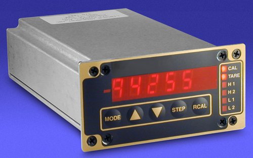
Features
- 1/8 DIN panel mount.
- Digital, 4½-place LED display
- 9 pin female D-sub (sensor)
- 15 pin male D-sub (input/output)
Specifications
Input
| Input Signal : | 5vdc Full Scale |
| Input Impedance: | >1 Megaohm |
| Input Bias Current: | < 1na |
Analog to Digital Converter
| Linearity: | +/- 0.01% FS +/- 1 digit |
| FS Accuracy: | +/- 0.01% FS +/- 1 digit |
| Zero Stability: | +/- 1 uv per deg C (typ) |
Readout
| Display type: | 0.4″ high efficiency red LEDs |
| Annuciators: | H1,H2,L1,L2, CAL & ZERO |
| Maximum Readout: | +/-99,999 |
| Polarity: | Minus sign displayed for negative readings. No sign for positive readings. |
| Decimal points: | Selectable via front panel switches. |
| Overrange Display: | Flashing display indicates input >10vdc |
| No Sensor Indication: | The display will flash overrange when sensor is not connected. |
Transducer Power Supply</h4>
| Volatge: | +/- 15 vdc +/- 5% |
| Current: | 250ma (minimum) short circuit current limited with thermal overload protection. |
Input Power
| Voltage: | 100,120,220 or 240 vac @ 50-60hz internal jumper selectable. |
| Current: | 150 ma (typ) |
| Fuse: | 500ma, 250 volt, rear panel accessible 5mm fuse. |
Package
| Type: | 1/18 DIN extruded aluminum housing with sheilded front panel switch assembly. |
Programmable Functions
| Program: | Sequences through the following program options. StPt (Setpoint Control Voltage) SPH1 (Alarm Setpoint High #1) SPL1 (Alarm Setpoint Low #1) SPH2 (Alarm Setpoint High #2) SPL2 ( Alarm Setpoint Low #2) HH (Hysteresis for High Alarm Setpoints) HL (Hysteresis for Low Alarm Setpoints) CAL (Full Scale Flow Calibration Value) dP (Decimal Point location) |
| StPt: | Flowmeter Control Voltage (0-5 vdc) can be set using the front panel Program switches. Setpoint voltage is automatically calculated using the programmed setpoint value (StPt) and the programmed full scale (CAL) value. Flowmeter output offset voltage is automatically compensated for whenever a ZERO function is activated. |
| Alarms: | (2) high and (2) low digital alarms are set via the front panel switches and activated whenever the alarm setpoints are exceeded. The appropriate front panel alarm annunciator will illuminate and open collector transistors will activate when the alarm setpoints are exceeded. |
| HH & HL: | (1) high and (1) low hysteresis value can be programmed providing up to 99 counts of digital alarm deadband. |
| Cal: | Full Scale Calibration value used during calibration. |
| dP: | x.xxxx,xx.xxx,xxx.xx and xxxx.x decimal point locations can be set using the Program switches. |
| Calibration: | Allows ZERO and CAL (Full Scale Calibration) functions. |
| Zero: | ZERO switch and rear panel D-Sub connector control line (low) activates display zeroing function over the full display range. |
| Cal: | CAL switch allows push button full scale calibration to CAL value. |


